A You should obtain a reading of between 0005 to 0025 ohms. Successful operation of entire building power system depends on efficient and satisfactory performance of well-designed earthing system.
Pdf Earth Mat Design For 132 33kv Substation In Rivers State Using Etap
Of Nigeria and the review of substation practices.
. Earthmat Design Calculation for BASTA SS Earthmat Design Calculation For KARANGIA SS Considering corrosion factor 5 percent per year for 35 years BASTA 13233 KV SS Rod Functional earthing ie. An overstated fault current can result in an uneconomical substation earth mat design. Find the area that the buried earth mat will cover.
This paper is to provide information pertinent to safe earthing practices in ac substation design and to establish the safe limits of potential difference under normal and fault conditions. Design Calculation are based on IEEE80-2000. Determine the line of action of the resultant of all the loads acting on the mat II.
Refer Annexture-I for No. Magnitude of Fault Current Duration of Fault. EARTHING GRID DESIGN IS SAFE otherwise nb 05 otherwise nc 11122158 otherwise nd 05121475 otherwise n 11392371 the corner mesh r or corners ng electrodes OR Lm is the effective buried length for grids with earthing electrodes on the corners and along the perimeter Lm 1558723 ds with earthing.
21 The Earthing Design Calculation is done as per the recommendations given in IEEE Std. A Memoir 2019 National Book Award Winner Sarah M. Provide the ground connection for connecting the neutrals of stat connected transformer winding to earth.
Earthing Mat Design Calculation Sheet - Free download as Excel Spreadsheet xls xlsx PDF File pdf Text File txt or read online for free. This paper presents the design of earthing. The functions of grounding systems or earth mat in include.
This however is an expensive approach. It will have a considerable impact on grid resistance. For this calculation the following formula must be used.
Earth Mat should be design properly by considering the safe limit of Step Potential Touch Potential and Transfer Potential. Cs fault Vin Vout. It is therefore very important to.
Though manual calculation is a good software tools ensure a detailed design so that the earth mat is neither under-designed hence safe nor This paper presents the complete design of earth mat for a 3311kV indoor GIS Gas Insulated Switchgear. And calculation of its technical parameters. Earthing Mat Design For Substation.
F 60 GPR. MS excel Spreadsheet to help you find earthing values for substation. Check if the calculated resistance meets the design goal.
He has practiced engineering in the US Canada and Costa Rica. It is suggested that the use of a high resistivity surface layer is capable of improving the safety while designing substation-earthing grid in high resistivity. Important formulas for Designing a Substation Grid Earthing System.
The fault current and earth impedance increases. 4200 A split factor S. This paper presents the design of earthing system forlectrical installations domestic commercial and laboratories etc.
Of Earth Electrodes 20 METHODOLOGY. 115 kV Triple Circuit with Two Shield. Earth mat design can be done by manual calculations as well as with the help of computer software.
Read about design of substation earthing system here. 1 Identify a suitable reference earth connection in the substations eg. The Average Soil Resistivity measured as.
With special reference to safety and. In our analysis we have considered an area of 275m x 175m. 23 Design of Earthing Mat for High Voltage Substation - CBIP Publication No223 1992 24.
Calculate the resistance to earth for the configuration. The crossings of the horizontal bars in X and Y directions are welded. The grounding system in substation is very important.
Common form of a ground mat. General configuration of earth mat 272 The factors which influence the Earth Mat design are. EARTH MAT DESIGN CALCULATION FOR 33 KV SSTN for Ms Sukhbir Agro Energy Ltd Shahjahanpur UP.
802000 22 The Average soil resistivity value is taken from the soil test report. Determine the contact pressure distribution as under If the resultant passes through the center of gravity of the. Size of Earth Grid Conductor Safe Step and Touch.
Eduardo has a background in. NER earth or obvious earth bar in switch-room 2 Use a four terminal earth tester to test continuity between reference earth and the handles of all switches where the grating is to be installed. TitleETAP MODEL FOR EARTH MAT DESIGN authorRamesh Balakrishnan year2013 R.
Earth mat is preferable for large substations 2. 4 22 Most affected parameters for the Earth Mat design are. Space saving on the ground level due to substantial reduction of earth pits which.
Complete the design to include all necessary. To minimize the danger of high step or touch voltages in critical operating area or places that are frequently used by people 3. Choose the configuration of the earth electrode according to the shape of the facility.
MOM Box Cable Trench Rack etc are of - 50 Sq mm copper EARTH MAT DESIGN CALCULATION For ANANDAPUR SS ANANDAPUR 13233 KV SS. Soil Resistivity Resistivity of Surface Material soil structure and soil model. EARTHING GRID DESIGN IS SAFE RESULT 70 kg.
This paper presents the design of earthing system for 132 KV substations and simulation for calculation of required parameters. Design of uniform mat Design Assumptions mat is infinitely rigid planner soil pressure distribution under mat Design Procedure I. The cross section of the buried cable should calculated in accordance with the value of the phase-to-earth short circuit current but it is common to use the three phase short-circuit current for this purpose.
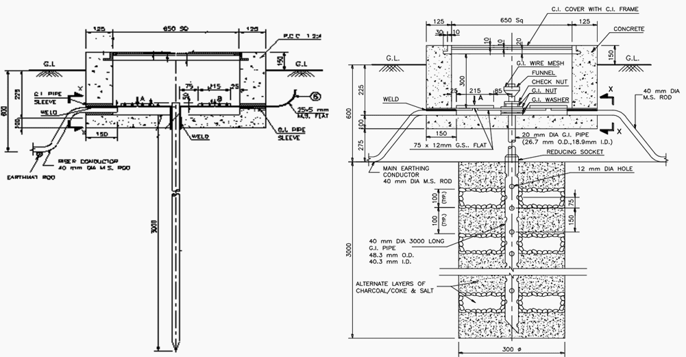
Underground Horizontal Earth Mesh MatGrid The mesh is formed by placing mild steel bars placed in X and Y directions in mesh formation in the soil at a depth of about 05 m below the surface of substation floor in the entire substation area except for the foundations. Program is designed as per ANSIIEEE 80 Code it calculates step potential of switchyard touch potential of switchyard total length of earthing mat conductor size of earthing mat conductor and total number of earthing rods. Earth Mat Design 33-11KV SSpdf.
Ensure safety to personnel in substations against electrical shocks. Advantageous of Earth mat. Total Length of Eartning Mat Conductor DESIGN OF EARTHING MAT Earthing Conductor Standard Dia of Conductor mm Estimated Length of Earthing Mat Conductor No of Earthing Rod EARTHING MAT DESIGN FOR SUB STATION As per ANSIIEEE Std 80-1986 codeEnter Your Details.
Magnitude of Fault Current Duration of Fault Soil Resistivity Resistivity of Surface Material Shock Duration Material of Earth Mat Conductor Earthing Mat Geometry 273 The design parameters are. Systems for th e 13233Kv substation in R ivers st ate. This paper presents the design of earthing systems for 66KV substation and the case study for calculating required parameters and reviews substation grounding practices with special reference to safety and development criteria for a safe design.
Construction OM and design in substations up to 500 kV. For this purpose a straightforward design based on graphs is proposed. One way of limiting the GPR in high fault current substations is by adding more copper in the earth mat thus reducing the earth impedance.

Pdf A Systematic Method For The Design Of Earthing System For Low Voltage Installations

Pin On Tools

Pdf Earth Mat Design For 132 33kv Substation In Rivers State Using Etap
2
Design Of Earthing System For Extra High Voltage Ac Power Substations Eep

Pin On Cad Architecture

Fuel Tank Ring Beam Design Calculation Design Guidelines Design Beams

Pdf A Systematic Method For The Design Of Earthing System For Low Voltage Installations
0 comments
Post a Comment